Developing the ADX Industrial Arduino, Balancing Automated Testing with Tactile Reliability
Developing the "ADX" Industrial Arduino: Balancing Automated Testing with Tactile Reliability
I am currently in the thick of developing ADX, an industrial-grade Arduino based on the ATtiny1616.
I’ve recently reached a major milestone in the circuit design for the initial "ADX Core V0" board. With the core architecture now settled, it was the perfect time to solidify a design philosophy that integrates shipping inspections with the end-user experience (UX). The core challenge? Finding the sweet spot between the efficiency of automated testing and the physical reliability required for industrial equipment.
The Dilemma: Pogo Pins vs. The "Click"
In the early stages, my goal was to maximize manufacturing efficiency through fully automated testing using pogo-pin jigs. The reasoning is sound: place test pads on the PCB, pop it into a jig, and let the electrical signals confirm the board's health. It’s the gold standard for mass production.
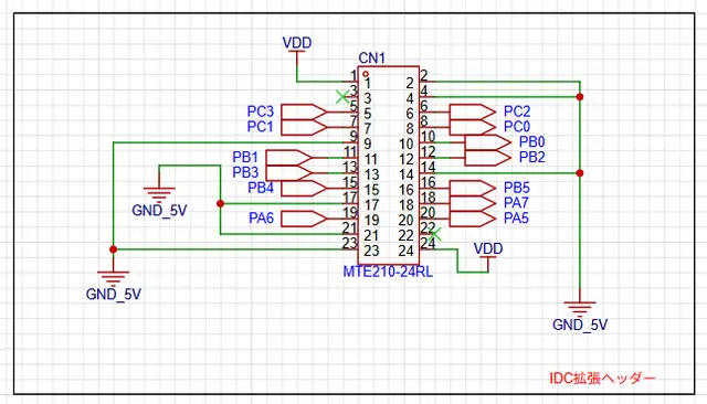
However, as I dove deeper into the ADX specs, I hit a fundamental snag. One of ADX’s standout features is its locking-lever IDC terminals.
Can electrical continuity alone guarantee the integrity of a mechanical connector? A pogo pin only confirms that a circuit is closed; it doesn't care if the IDC box header lever is stiff or if a molding defect prevents the lock from engaging. For an industrial device, a connector that fails to lock is a fatal flaw. I ultimately came to the conclusion that the inspection must encompass the very terminal the user will touch.
The Move Toward Strategic Semi-Automation
For ADX Core V0, I’ve decided to resist the temptation of "total automation." Instead, we are implementing a test flow that involves physically plugging an IDC cable into the board.
Since confirming the "feel" of a locking lever is a subjective, tactile task that machines struggle to replicate, I shifted the design philosophy from "full automation" to a division of labor between human and machine.
In this Strategic Semi-Automation model:
- Humans handle the high-precision physical check (inserting the cable).
- Machines handle logic testing, power cycling, and board feeding.
By intentionally retaining a manual step, we ensure the physical reliability of the connectors while automating every other repetitive task. For ADX, this is the most logical path to quality.
UPDI Protection and the UX of Safety
This integration of testing and UX also dictated how I handled the UPDI (Unified Program and Debug Interface).
From a pure efficiency standpoint, it would be easiest to bundle all signals—including programming pins—into a single IDC connector for "one-click" testing and flashing. However, the ATtiny1616’s UPDI pin is a double-edged sword. While powerful (capable of 12V pulse resets), it can be sensitive to external noise. Exposing UPDI on the main IDC header felt like a long-term reliability risk in noisy industrial environments.
My Solution: I’ve isolated the UPDI, VDD, and GND into a dedicated 3-pin interface.
Rather than using standard pin headers, I chose pin sockets. This serves two purposes:
- Short-circuit prevention: No exposed pins means no accidental shorts during handling.
- ESD Mitigation: The socket housing acts as a physical barrier, minimizing the risk of Electrostatic Discharge (ESD) from human contact.
Choosing a socket over a header for the sake of durability and safety is a prime example of what I call Industrial UX.
Final Thoughts
Spending this much time obsessing over the "gritty details" of the inspection process while the design is still in V0 might seem like a detour. However, I believe that baking these "on-the-ground realities" into the schematic now is what defines the product's eventual maturity.
By navigating the trade-offs between efficiency and reliability one by one, ADX is steadily evolving into a refined, robust tool for the industry.
#adx #manufacturing #circuit #design #ux #pinout #test